
MPLS introduction & Basic configuration
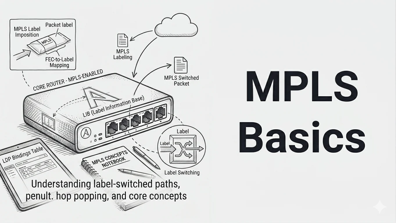
Multi protocol labels switching (MPLS) uses labels to forward packets, instead of traditional routing. Alternatively to having each router looking up the destination in each packet’s header and forwarding it to the next hop, routers can simply switch packets based label value.
Once a label distribution protocol (LDP) session is established between routers, labels are exchanged for prefixes and stored in the forwarding equivalence class table (FEC). A subset of packets to be forwarded along the same path and treatment.

Four bytes label is inserted between layer2 header and layer3 packet.

Router role:
- LSR Label Switch router a router which supports MPLS
- Ingress LSR Receives unlabeled packets and push a label on it.
- Egress LSR Pop a label from a packet.
- Intermediate LSR Switch labelled packets.
It is sometimes said that one of the benefits of MPLS is speeding up packet forwarding, since this operation no longer relies on routing table lookups. Although this might have been true in the old days, it no longer holds. Current routers architecture decouple data and control planes, offloading the CPU from the forwarding function.
So what are the real benefits and advantages of deploying MPLS ?
For starters, deploying MPLS will remove the need for running BGP on core nodes. This is referred to as BGP free core, where BGP is only running on edge nodes and often a set of route reflectors.
Another advantage is the possibility to implement VPN, over one AS or more (Inter-AS VPN). This design allows a given provider to segregate its routing context per VPN set. Traffic engineering (TE) is another benefit, whereby traffic path can be manipulated and engineered due to capacity constraints or links quality.
And finally AToM, which is an acronym for Any Transport over MPLS. Layer 2 VPNs (L2VPN) are a great application of AToM.
MPLS configuration
At a basic level, configuring MPLS is rather straight forward.
You must enable or have an IGP running already and enable LDP globally. Define or hard code LDP update source, this is typically default to a used Loopback zero. And finally, enable LDP on each interface adjacent to an LSR.
There is also the option to auto configure LDP on each interface running IGP.
!!! IOS based config !!!
interface GigabitEthernet0/1
 ip address 10.1.1.1 255.255.255.254
 ip router isis NL
 mpls ip
!
router isis NL
 net 01.0172.0016.0001.0001.00
 is-type level-2-only
 passive-interface Loopback0
!
mpls ldp router-id Loopback0
!!! XR based config !!!
router isis NL
is-type level-2-only
net 01.0172.0016.0001.0004.00
address-family ipv4 unicast
mpls ldp auto-config
!
!
mpls ldp
router-id 172.16.1.4
!Notice how for XR config, I chose to auto-configures MPLS on any interfaces running that particular IGP process. Another difference between IOS and XR is the way router-id is configured.
For validation and verification following commands can be used.
!!! IOS based config !!!
sh mpls interfaces
Interface              IP            Tunnel   BGP Static Operational
GigabitEthernet0/1     Yes (ldp)     No       No  No     Yes
GigabitEthernet0/2     Yes (ldp)     No       No  No     Yes
!
!
P2#sh mpls ldp neighbor
    Peer LDP Ident: 172.16.1.2:0; Local LDP Ident 172.16.1.3:0
        TCP connection: 172.16.1.2.646 - 172.16.1.3.54388
        State: Oper; Msgs sent/rcvd: 1543/1542; Downstream
        Up time: 22:14:24
        LDP discovery sources:
          GigabitEthernet0/1, Src IP addr: 10.1.1.3
        Addresses bound to peer LDP Ident:
          192.168.1.182   10.1.1.0        10.1.1.3        172.16.1.2
    Peer LDP Ident: 172.16.1.4:0; Local LDP Ident 172.16.1.3:0
        TCP connection: 172.16.1.4.58119 - 172.16.1.3.646
        State: Oper; Msgs sent/rcvd: 34/33; Downstream
        Up time: 00:18:08
        LDP discovery sources:
          GigabitEthernet0/2, Src IP addr: 10.1.1.5
        Addresses bound to peer LDP Ident:
          192.168.1.184   10.1.1.5        10.1.1.6        172.16.1.4
!
!
P2#sh mpls forwarding-table
Local      Outgoing   Prefix           Bytes Label   Outgoing   Next Hop
Label      Label      or Tunnel Id     Switched      interface
16         Pop Label  172.16.1.4/32    0             Gi0/2      10.1.1.5
17         Pop Label  172.16.1.2/32    0             Gi0/1      10.1.1.3
19         Pop Label  10.1.1.0/31      1140          Gi0/1      10.1.1.3
20         16         172.16.1.1/32    0             Gi0/1      10.1.1.3
21         24005      172.16.1.5/32    0             Gi0/2      10.1.1.5
22         Pop Label  10.1.1.6/31      1140          Gi0/2      10.1.1.5
!
!
!!! XR based config !!!
RP/0/0/CPU0:P3#sh  mpls ldp interface
Tue Jan 21 12:05:17.511 UTC
Interface GigabitEthernet0/0/0/0 (0x40)
   VRF: 'default' (0x60000000)
   Enabled via config: IGP Auto-config
Interface GigabitEthernet0/0/0/1 (0x60)
   VRF: 'default' (0x60000000)
   Enabled via config: IGP Auto-config
!
!
RP/0/0/CPU0:P3#sh  mpls ldp neighbor
Tue Jan 21 12:06:05.398 UTC

Peer LDP Identifier: 172.16.1.3:0
  TCP connection: 172.16.1.3:646 - 172.16.1.4:58119
  Graceful Restart: No
  Session Holdtime: 180 sec
  State: Oper; Msgs sent/rcvd: 38/39; Downstream-Unsolicited
  Up time: 00:22:22
  LDP Discovery Sources:
    IPv4: (1)
      GigabitEthernet0/0/0/0
    IPv6: (0)
  Addresses bound to this peer:
    IPv4: (4)
      10.1.1.2       10.1.1.4       172.16.1.3     192.168.1.183
    IPv6: (0)

Peer LDP Identifier: 172.16.1.5:0
  TCP connection: 172.16.1.5:19855 - 172.16.1.4:646
  Graceful Restart: No
  Session Holdtime: 180 sec
  State: Oper; Msgs sent/rcvd: 20/20; Downstream-Unsolicited
  Up time: 00:06:42
  LDP Discovery Sources:
    IPv4: (1)
      GigabitEthernet0/0/0/1
    IPv6: (0)
  Addresses bound to this peer:
    IPv4: (3)
      10.1.1.7       172.16.1.5     192.168.1.185
    IPv6: (0)
!
!
RP/0/0/CPU0:P3#sh  mpls forwarding
Tue Jan 21 12:06:16.937 UTC
Local  Outgoing    Prefix             Outgoing     Next Hop        Bytes
Label  Label       or ID              Interface                    Switched
------ ----------- ------------------ ------------ --------------- ------------
24000  Pop         172.16.1.3/32      Gi0/0/0/0    10.1.1.4        2450
24001  17          172.16.1.2/32      Gi0/0/0/0    10.1.1.4        0
24002  Pop         10.1.1.2/31        Gi0/0/0/0    10.1.1.4        0
24003  19          10.1.1.0/31        Gi0/0/0/0    10.1.1.4        1040
24004  20          172.16.1.1/32      Gi0/0/0/0    10.1.1.4        0
24005  Pop         172.16.1.5/32      Gi0/0/0/1    10.1.1.7        34848
In this post MPLS packet flow, you can learn more about label switching in an MPLS network. And follow the trail hop by hop, using Cisco show commands.